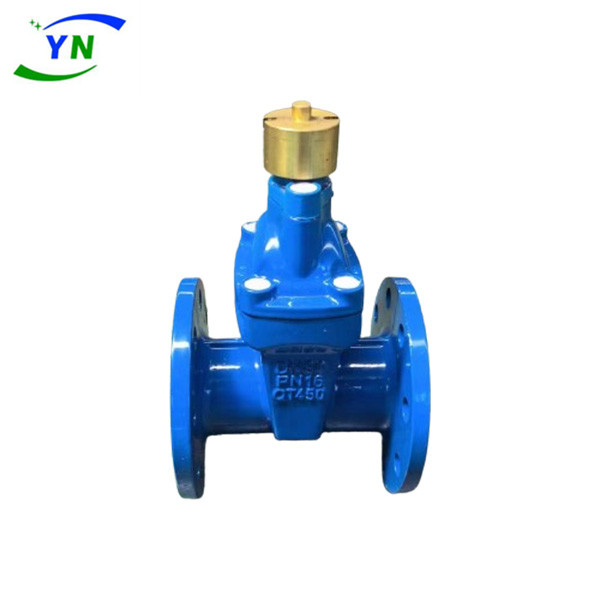
Magnetic Ductile Iron Elastic Seat Sealing Gate Valve
Related recommendations : Concealed Rod Underground Spring Seat Sealing Gate Valve | Soft Sealed Concealed Stem Gate Valve | Large Diameter Turbine Drive Gate Valve

The bottom of the magnetic ductile iron elastic seat sealed gate valve adopts the same flat bottom valve seat design as the water pipe, which does not produce debris accumulation, has a small flow resistance coefficient, and a smooth channel. The magnetic locking elastic seat sealing gate valve body is coated with non-toxic epoxy resin inside and outside to prevent corrosion and rust. It can not only be used for domestic water, but also in sewage treatment systems. Widely used as a regulating and throttling device in fluid pipelines such as tap water, sewage, construction, petrochemicals, food, medicine, textiles, electricity, ships, metallurgical energy systems, etc.
The opening and closing component is a plug shaped valve disc, with a flat or conical sealing surface. The valve disc moves in a straight line along the centerline of the fluid. The movement forms of the valve stem include the lifting rod type (valve stem lifting, handwheel not lifting), as well as the lifting rotating rod type (handwheel and valve stem rotating together to lift, nut installed on the valve body). The corrugated tube globe valve is only suitable for fully open and fully closed, and cannot be adjusted or throttled.
Magnetic ductile iron elastic seat sealing gate valve belongs to the forced sealing type valve, so when the valve is closed, pressure must be applied to the valve disc to force the sealing surface to not leak. When the medium enters the valve body from below the valve disc, the resistance that needs to be overcome by the operating force is the friction force between the valve stem and the packing and the thrust generated by the pressure of the medium. The force to close the valve is greater than the force to open the valve, so the diameter of the valve stem should be larger, otherwise it will cause the valve stem to bend. In recent years, with the emergence of self sealing valves, the medium flow direction of globe valves has changed from above the valve disc to enter the valve chamber. At this time, under the pressure of the medium, the force to close the valve is small, while the force to open the valve is large, and the diameter of the valve stem can be correspondingly reduced. At the same time, under the action of the medium, this form of valve is also relatively tight. The "Three Modernizations" of valves in our country once stipulated that the flow direction of globe valves should be from top to bottom.

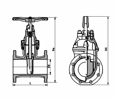
Main dimensions and weight:
| model | DNmm | L | D1 | D | Z-Φd | H | ||
| 1.0MPa | 1.6MPa | 1.0MPa | 1.6MPa | |||||
|
RVC(H)X Z45X Z41X | 50 | 180 | 125 | 165 | 4-Φ18 | 268 | ||
| 65 | 190 | 145 | 185 | 4-Φ18 | 296 | |||
| 80 | 240 | 160 | 200 | 8-Φ18 | 340 | |||
| 100 | 250 | 180 | 235 | 8-Φ18 | 367 | |||
| 125 | 254 | 210 | 250 | 8-Φ18 | 424 | |||
| 150 | 280 | 240 | 290 | 8-Φ23 | 515 | |||
| 200 | 300 | 295 | 340 | 8-23 | 12-23 | 550 | ||
| 250 | 380 | 350 | 355 | 410 | 12-23 | 12-25 | 685 | |
| 300 | 400 | 400 | 410 | 460 | 12-23 | 12-25 | 760 | |
| 350 | 430 | 460 | 470 | 520 | 16-23 | 16-25 | 845 | |
| 400 | 406 | 515 | 525 | 580 | 16-26 | 16-30 | 945 | |
| 450 | 432 | 565 | 585 | 640 | 20-26 | 20-30 | 1020 | |
| 500 | 457 | 620 | 650 | 715 | 20-26 | 20-34 | 1140 | |
| 600 | 508 | 725 | 770 | 840 | 20-30 | 20-36 | 1320 | |


