Y Strainer
Related recommendations : Y-shaped Filter With Ball Valve | Y Strainer | German Standard Spherical Flange Bottom Valve(dn350)

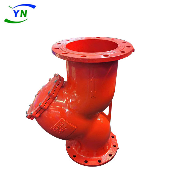
Y Strainer are an indispensable filtering device in pipeline systems for conveying media. Y Strainer are usually installed at the inlet of pressure reducing valves, relief valves, constant water level valves, or other equipment to remove impurities in the medium and protect the normal use of valves and equipment. The Y-shaped filter has the characteristics of advanced structure, low resistance, and convenient discharge. The Y-type filter is suitable for media such as water, oil, and gas. The general water supply network is 18-30 mesh, the ventilation network is 10-100 mesh, and the oil supply network is 100-480 mesh. The basket filter mainly consists of a connecting pipe, a main pipe, a filter blue, a flange, a flange cover, and fasteners. When the liquid enters the filter basket through the main pipe, solid impurity particles are blocked inside the filter basket, while clean fluid is discharged through the filter basket and through the filter outlet.
A Y Strainer is a Y-shaped filter, with one end allowing water and other fluid to pass through and the other end settling waste and impurities. It is usually installed at the inlet of a pressure reducing valve, relief valve, constant water level valve or other equipment. Its function is to remove impurities from the water and protect the normal operation of the valve and equipment. The water to be treated by the filter enters the body through the inlet, and impurities in the water deposit on the stainless steel filter screen, resulting in a pressure difference. By monitoring the pressure difference changes at the inlet and outlet through a pressure difference switch, when the pressure difference reaches the set value, the electronic controller sends signals to the hydraulic control valve and drive the motor, triggering the following actions: the motor drives the brush to rotate, clean the filter element, and at the same time, the control valve opens for drainage. The entire cleaning process only lasts for a few seconds. When the cleaning is completed, the control valve is closed, the motor stops rotating, and the system returns to its initial state, starting the next filtering process. After the installation of the equipment, technicians carry out debugging, set the filtration time and cleaning conversion time. The water to be treated enters the machine body through the inlet, and the filter starts working normally.

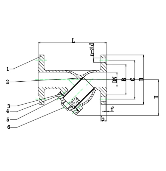
Part & Materials
| No | Part | Material |
| 1 | Body | Ductile Iron GGG50 |
| 2 | Screen | Stainless Steel |
| 3 | O-ring | NBR/EPDM |
| 4 | Cover | Ductile Iron GGG50 |
| 5 | Bolts | A2-70 |
| 6 | Plug | Carbon Steel |
Dimensions(mm)
| DN | L | D | C | B | n-d | b | f | H | |||||
| PN10 | PN16 | PN10 | PN16 | PN10 | PN16 | PN10 | PN16 | PN10 | PN16 | ||||
| DN40 | 200 | 150 | 110 | 84 | 4-19 | 19 | 3 | 110 | |||||
| DN50 | 230 | 165 | 125 | 99 | 4-19 | 19 | 3 | 120 | |||||
| DN65 | 290 | 185 | 145 | 119 | 4-19 | 19 | 3 | 155 | |||||
| DN80 | 310 | 200 | 160 | 133 | 8-19 | 19 | 3 | 175 | |||||
| DN100 | 350 | 220 | 180 | 154 | 8-19 | 19 | 3 | 230 | |||||
| DN125 | 400 | 250 | 210 | 184 | 8-19 | 19 | 3 | 280 | |||||
| DN150 | 480 | 285 | 240 | 210 | 8-23 | 19 | 3 | 340 | |||||
| DN200 | 600 | 340 | 295 | 265 | 8-23 | 12-23 | 20 | 3 | 430 | ||||
| DN250 | 730 | 405 | 350 | 355 | 319 | 12-23 | 12-28 | 22 | 3 | 450 | |||
| DN300 | 850 | 460 | 400 | 410 | 370 | 12-23 | 12-28 | 24.5 | 4 | 520 | |||
| DN350 | 980 | 520 | 460 | 470 | 429 | 16-23 | 16-28 | 26.5 | 4 | 610 | |||
| DN400 | 1100 | 580 | 515 | 525 | 480 | 16-28 | 16-31 | 28 | 4 | 760 | |||
| DN450 | 1200 | 640 | 565 | 585 | 530 | 548 | 20-28 | 20-31 | 30 | 4 | 850 | ||
| DN500 | 1250 | 715 | 620 | 650 | 582 | 609 | 20-28 | 20-34 | 31.5 | 4 | 960 | ||
| DN600 | 1450 | 840 | 725 | 770 | 682 | 720 | 20-31 | 20-37 | 36 | 5 | 1060 | ||
Technical Data
| No | Description | Specification |
| 1 | Nominal Dia | DN40-DN600 |
| 2 | Nominal Pressure | PN10&PN16 |
| 3 | Valve Design Standard | DIN3202 F1 |
| 4 | Face to Face Standard | EN558&ISO5752 Series-48 |
| 5 | Flange Standard Conformity | DIN2533 |
| 6 | Testing Standard | DIN3230 |
| 7 | Expoxy Coating | Epoxy powder coating with minimum thickness of 250 microns inside and outside. |
| 8 | Testing Pressure | |
| Shell Test | PN*1.5Times | |
| 9 | Working Temperature(Max) | 80℃ |


