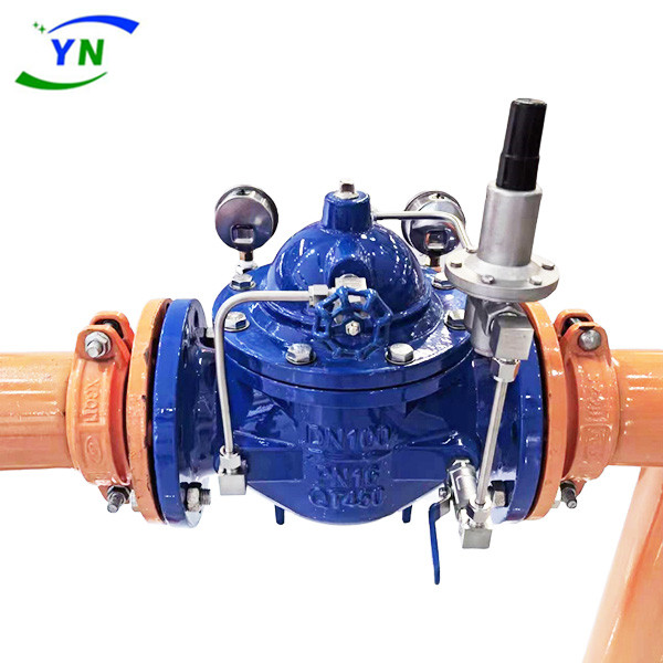
Pilot-operated Reducing Valves
Related recommendations : Pilot-operated Reducing Valves | Slow Closing Silencing Check Valve | Flow Control Valve

Pilot-operated reducing valves is an intelligent hydraulic control valve that utilizes the energy of the medium itself to regulate and control pipeline pressure. Pilot-operated reducing valves are used in domestic water supply, fire water supply, and other industrial water supply systems. By adjusting the pressure reducing pilot valve of the regulating valve, the outlet pressure of the main valve can be adjusted. The outlet pressure does not change due to changes in inlet pressure and flow rate, and can be safely and reliably maintained at the set plant. The set value can be adjusted as needed to achieve pressure reduction. This valve has precise pressure reduction, stable performance, and is safe and reliable.
When the valve supplies water from the inlet end, the water flows through the needle valve and enters the main valve control room, and the outlet pressure acts on the pilot valve through a conduit. When the outlet pressure is higher than the set value of the pilot valve spring, the pilot valve closes. The control room stops draining, and at this time, the pressure inside the main valve control room increases and the main valve is closed, and the outlet pressure no longer increases. When the outlet pressure of the valve drops to the set pressure of the pilot valve spring, the pilot valve opens and the control room discharges water downstream. Due to the displacement of the pilot valve system being greater than the water inflow of the needle valve, the pressure in the control room of the main valve decreases. The inlet pressure causes the main valve to open. In a stable state, the inlet and outlet of the control room are the same, the main valve opening remains unchanged, and the outlet pressure is stable. Adjust the pilot valve spring to set the outlet pressure.
Features of pilot operated pressure reducing valves
1. Novel and reasonable structure, reasonable use of hydraulic principles in control theory;
2. Stable and reliable work, with high traffic flow;
3. Valve disc fast opening and slow closing, no water hammer impact (adjustable closing time);
4. High precision and wide adjustment range for voltage reduction and stabilization;
5. Good sealing performance and long service life;
6. Easy installation and maintenance.
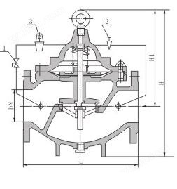
Product structure diagram:

Product parameters:
| Main performance parameters: | |
| nominal pressure | PN1.0/1.6/2.5Mpa |
| Temperature | ≤80℃ |
| Applicable Medium | Water, clear water |
| Standard for flange length | GB/T 17241.6 |
| Test pressure standard | GB/T 13927;AP1598 |
| DN(mm) | L(mm) | H1(mm) | H(mm) |
| 40 | 200 | 272 | 237 |
| 50 | 203 | 282 | 254 |
| 65 | 215 | 292 | 272 |
| 80 | 241 | 310 | 282 |
| 100 | 270 | 330 | 303 |
| 125 | 300 | 358 | 344 |
| 150 | 333 | 385 | 385 |
| 200 | 400 | 438 | 437 |
| 250 | 480 | 490 | 532 |
| 300 | 550 | 550 | 600 |
| 350 | 622 | 617 | 677 |


